This page describes how we made the main switching circuits for the 2, 4 and 8 channel boxes. The 2 and 4 channel boxes are utilized under the trees, the roof, and by the driveway for the scrolling lights. The 8 channel boxes are used for the lights on the roof grid.
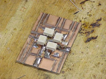
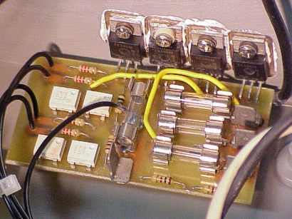
The main switching circuit consists of an Opto-Coupler, 2 resistors, and a Triac. The first set of boards created, for the show in 2000, were all hand carved. In the following years, these boards were custom built using etching soloutions. The board here houses 4 Opto-Couplers, and 4 current limiting resistors. It's in the beginning stage which is why there aren't any triacs yet.
Here, we see all the components attached to the board. The boards' traces are tinned to help increase the ampacity rating. This board is now ready for the next step, which is placing the wires on it.
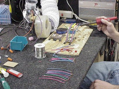
This pic shows the general setup we had for that year at our soldering desk! We were soldering the power leads to the board and adding a ground wire for the control circuits. A ventilating fan was setup to keep the soldering fumes out of our lungs.
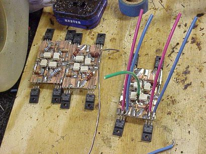
Just another pic of the 4 Channel boards. Here we had 3 sets waiting to have the power leads soldered on.
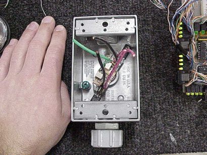
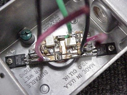
This is a 2 channel board mounted in an aluminum duplex box. We decided to use the box as a heat sink for the triacs because aluminum is a very good heat conductor, and since our weather is usually about -15 Celsius, the metal is generally kept cool. Heat is the number one killer of electronics!
A closer view of a 2-channel board mounted to a singal-gang box. You can see the machine screws that connect the triacs to the box. There is a nut and spring washer on the backside, along with weathertight sealant, of course! The triacs have thermal paste applied to the backs which improves the heat transfer to the aluminum box.
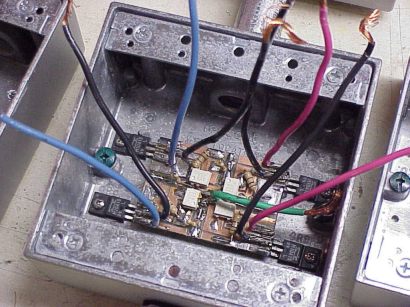
Here's a 4-channel board installed in a 2-gang metal box. The control wires are added in the next picture.
(2) four-channel boxes are joined together to create an 8-channel setup. This was the largest setup we had in 2000 and was pretty power hungry since this box was powering 1500 watts alone. We can see the 24 AWG wires sticking out the boxes, these are the control wires that lead to the buffer boards in the house.
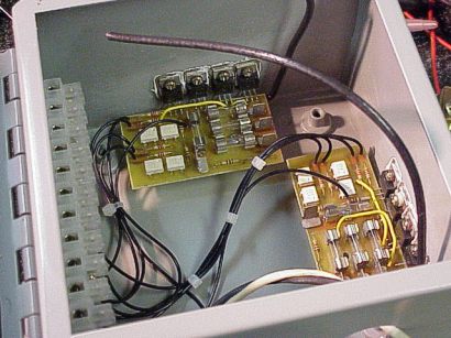
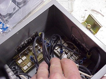
This is one of our 8-channel boxes that is used to power the roof grid. Like all of our boxes, this one was designed to be entirely water tight and was fused to prevent accidental triac overloading! Two boards of 4-channels were placed in the box, and again, the box was used as a heat sink to keep things cool. We decided to start using quick disconnects and spade terminals (for the power connections), so we could easily remove a board for quick repair.
Another layout showing (2) boards installed, and a terminal strip for the control wire connections.
Here, we see all the wires are installed with the spade terminal connections.
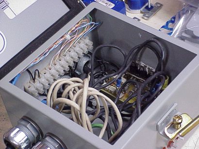
Similar to the above picture, this view doesn't have the hand in it, but also shows the low voltage terminal strip.
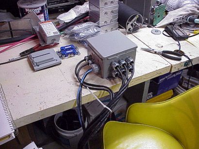
The 8 channel box is ready to go! (1) 14 awg, 3-conductor SOOW water-resistant wire feeds the box, while multiple 16awg wires exit the box, each acting as an individual channel.