| Home |
| What's New |
| Videos |
| Pictures |
| Donations |
| Webcams |
| Sponsors |
| About us |
| Contact |
| Archives |
| How we do it |
| Quick facts |
| Awards |
| Comments |
| Credits |
| FAQs |
| Lost/Found |

16 and 24 Channel Boxes
| Setup Status Power Distribution Computer Control Buffer Boards Channel Boxes Snowball Fight Driveway Arches |
Donation Box Grass Grid Roof Grid LED Mega Tree Trees Leaping Arches |
The following pictures show the creation of (2) control boxes. (1) is a 16-channel box that controls the snowmen, while the other is a 24-channel box that controls the left grass grid (20 channels are used while 4 are spare).
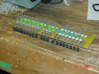 |
These are all the PC boards completed and ready to be installed in the weather sealed boxes. There are (2) 16 channel boards, and a 6 channel board. |
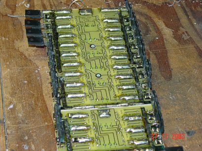 |
This shows the back of the boards. The boards' high voltage traces are soldered to provide more current flow. The high voltage lines are kept entirely away from the low voltage lines to prevent contact between the two. You can see the thick solder joints at the sides of the boards, and the thinner ones at the center. The center ones are about ¼" away from the outer ones, and the opto-isolator is what separates them. |
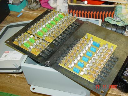 |
These are the boards being mounted onto the steel plates which will sit in the boxes. One 16 channel board is places with a 6 channel board, this created our 24 channel box. The other is simply a 16 channel board. |
 |
Here, we are mounting aluminum heat sinks to "sandwich" the triacs between the steel plate and the heat sinks. The Triacs have isloated tabs, which mean they can be heat-sinked to conductive surfaces without requiring insulators. The heat sink will provide the cooling required by the triacs in order to handle the rated loads. |
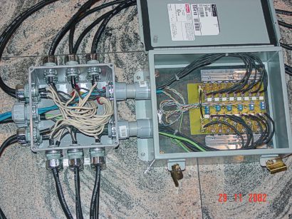 |
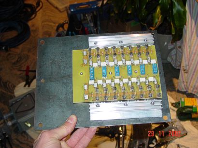
Neatness is the name of the game with us. This is the final product of the 16 channel box. This box is joined to a 6"x6" PVC pull box which is where the high voltage wires are connected. This makes things a lot easier for us to wire, and to trouble shoot if there is a problem with the circuits. |
 |
A close up pic of the 16 channel box shows the blue connectors in the center, which are the control inputs for the individual channel controls. The black wires are all 16 gauge, except for the supply wire which is 12 Gauge (bottom right). The jumper in the center joins the supply of the left and right section of the board. If the box ever needs to pump out more power, another supply line can be brought into the box. The jumper could then be disconnected and one supply line would feed each side of the board. Currently we only require 1 circuit to run all 16 channels, but in the future we may need to change this to 2 power circuits, each running 8 channels. |
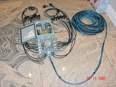 |
A zoomed out pic shows the general design of the 16 channel box. As you can see, there are 16 individual female sockets coming out of the secondary box, and one main power/control wire which is fairly long. ALL OUR BOXES ARE WATERTIGHT! |
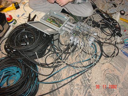 |
WHAT A MESS! Remember, the name of the game is neatness, but this is required in order for us to make it neat. This is the wiring status of the 24 channel box. Look at the amount of wire on the left! |
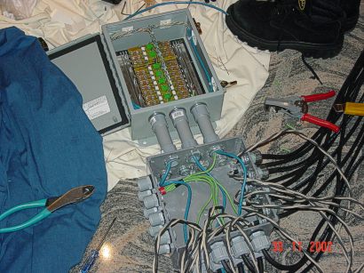 |
This 24 channel box has over 1000 bulbs to power. This requires over 5,000 Watts which is too much for a single 15amp/120v outlet to supply. Therefore, we had to incorporate (4) supply circuits in this box. There is one big trick to doing this though; ALL the neutral wires must be joined to the correct circuits, otherwise the Ground Fault Circuit Interrupters (GFCI) will not work properly. So the first 8 channels are on circuit 1, and the first 8 neutrals are on Neutral circuit 1. We cannot use a common neutral, as the GFCI's are continuously monitoring the current loss between the neutral and the load. |
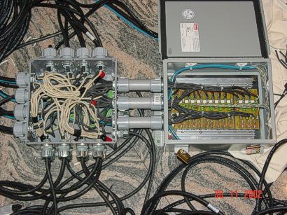 |
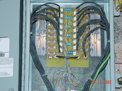
The 24 channel box is ready to be tested and sealed up! Look how tidy those connections are. |
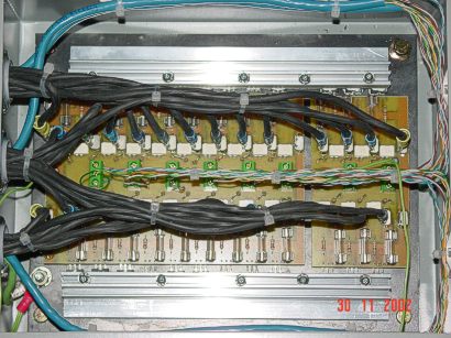 |
Notice there are 3 control wire bundles. Each set controls 8 channels, the common for all channels is the ground. If the ground is not good, then we won't be able to power up the circuits. This is good for ground checks, and double checks that we have proper grounds. |